When an electrical device is switched on it requires a high input current which is termed as inrush current. The reason is on start the inductive and capacitive components draw current many times higher than their normal average current. This high peak of current on just power on moment decays gradually and then after a few milli-seconds goes to average state of current consumption. The inrush current is basically due to charging of discharged inductive and capacitive components. The same is true for DC circuits. This high peak of inrush currents blows-off the over current protection devices such as fuses, switches-off the circuit breakers and may damage input power cables as well as the other components. The proper placement of input inrush current limiter saves the electrical devices and retains the overcurrent protections intact.
For the circuit and PCB design, the basic principle of incorporating the inrush current limiting device is that it is used in series with the load. The device should limit the peak current for a very small fraction of time and then later on it would pass the continuous current without any restriction. This continuous current is actually the required necessary operating current for the load. The inrush current limiter functions for both states, reducing the peak value of the current and then allow flow of average current without interruption, which is achieved by using an NTC thermistor i.e. a temperature dependent resistor. An NTC thermistor has a negative temperature coefficient i.e. the resistance decreases as the temperature of the device increases and the vice versa. It has a sufficient large resistance (generally in a few ohms range) at room temperature that limits the switch on sudden high current. After passing the high peak current it heats up and due to negative temperature coefficient it reduces its resistance that allows flow of average current. The appropriate examples of a thermistor inrush current limiter is found with the switch mode power supplies used with personal computers, LED/ LCD TVs and monitors etc. The thermistor offers a room temperature high resistance (2 to 5Ω) tills the input capacitors and inductors are charged and then a low resistance (a fraction of ohm) for the continuous operation. The current flow is proportional to the heat dissipation which is directly proportional to the body disc size of the device i.e. larger (smaller) the disc size results more (less) heat dissipation. A current limiter thermistor is generally available with large disc size whereas a temperature sensing thermistor, another popular application of thermistors, is available in large resistance values but in small size or even SMD chip package. A thermistor works equally for AC and DC circuits and in hot or neutral/ return current path.
In Figure 1 the shape of an inrush current limiting NTC thermistor is shown with varying disc size.
Figure 1: Inrush current limiter NTC thermistor

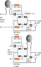
In Figure 2 a schematic is shown where thermistors are used for current limiting applications in two different paths of current.
Figure 2: Two different schemes of NTC thermistor current limiter usage for an ordinary load

Comments
Post a Comment