The smoke detectors are of great use when in need to detect any kind of smoke. The smoke may either be in case of fire or the smoke coming from cigarettes inside a building which may cause fire. Smoke detectors are of the basic precautionary measures in every building either under construction or fully constructed. This is because the smoke detectors are able to detect or sense smoke and then alarm is generated to let the authorities know about possible fire situation. This is how the fire is then handled within no time saving precious lives and stuff inside buildings.
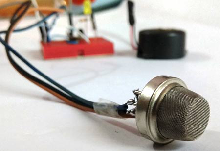
This project “Smoke detecting circuit” is being built without the use of a microcontroller. This is why this project is very easy and one can accomplish it without having high tech instruments of laboratories. The circuit is triggering the buzzer at the time when it detects the smoke or any fire nearby and alarm is generated. The circuit is comprising of the smoke detecting gadget which is MQ6 smoke also known as the Gas Sensor for the detecting of the level of smoke or fire. The sensing gadget MQ6 gas is also capable of detecting other elements such as Alcohol, Methane, and LPG etc. A simple transistor is being used for the triggering of the buzzer which is BC547 NPN transistor.

Safety precautions
The smoke sensing circuit is very sensible to all kinds of smoke, therefore you need to be very careful if you are having the sensor circuit in house or room and you are a regular smoker. This is because the sensor circuit will trigger the alarm or buzzer each time it senses the smoke of the cigarettes.
Notes
- The circuit is working on very low voltages.
- There is no need of having additional capacitors in the circuit.
- There is a need of variable DC supply in the circuit.
Components Required
The following are the basic components required in order to make the smoke detecting circuit.
- Bread Board
- BC547
- 10k POT
- Smoke Sensor (MQ6)
- Resistors of 1K
- Variable Power Supply
- Connecting wire
- Buzzer
- LED
- Jumper wire
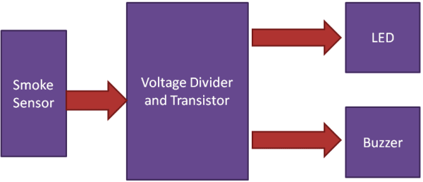
Chart Flow Diagram
The following is the chart flow diagram.

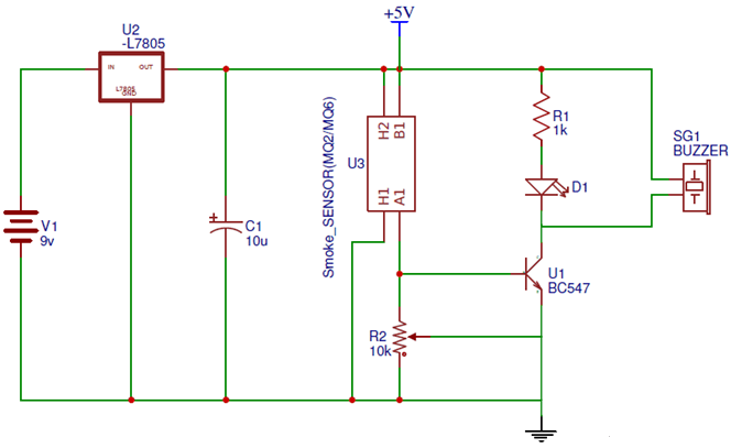
Basic Circuit Diagram

Working Principle
The circuit is having the MQ6 smoke also known as the Gas sensor gadget which is used for the smoke or fire detecting in the air. The transistor i.e. BC547 NPN is used for the buzzer or alarm trigger. The 10K potentiometer is used for the calibration of the circuit whereas the circuit is designed in order to have a voltage divider circuit being used with the MQ6 smoke sensor and the potentiometer. The value of the MQ6 is changing whenever it senses smoke as it is having a resistance.
The transistor operating properties are being used to work in the circuit of the smoke detection. The NPN BC 547 transistor is being used which is turned ON only at 0.7V at its base and the topology being used in the circuit is of voltage divider biased. The potentiometer is being used for the calibration purposes. Whenever voltage is applied at the base terminal which is less or greater than the 0.7V which would turn ON the transistor, the smoke sensor would sense the smoke and reduce the resistance of the device i.e. MQ6 smoke detector and due to this decrease in the resistance the voltage across the base of the BC547 is increased to 0.7V. This in turns make the transistor ON and LED lights up and the buzzer is triggered to start beeping. In case when the smoke is vanished the detector is made OFF and the voltage across the base of the transistor is reduced to a value below than 0.7V.
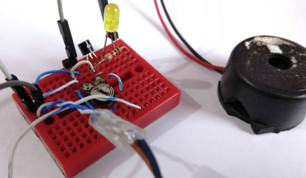
Photo of the Smoke Detecting Circuit

Comments
Post a Comment